 |


| Quantity: | |
|---|---|


It features excellent chemical stability, smooth inner wall, low fluid resistance, anti-scaling, wear resistance, negative pressure resistance and wide temperature adaptability. It can replace metal materials such as stainless steel, copper and aluminum, as well as non-metallic lining materials including rubber lining, plastic lining, PTFE lining, enamel lining and FRP. Stable production process extends maintenance cycle, improves product quality and reduces overall operating costs.
Glass Lined Steel Complete Data Sheet
Product Basic Introduction
Category | Details |
|---|---|
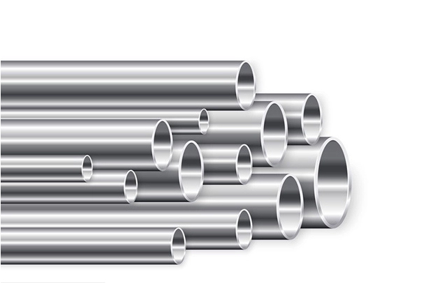
Product Molding Principle | Glass-lined steel is made by lining molten glass onto the inner surface of preheated carbon steel straight pipes, fittings, equipment and valves. The glass adheres firmly to the inner wall to form a steel-glass composite structure. |
Application Industries | Widely applied in chemical industry, papermaking, pharmaceutical production, military industry, metallurgy, power plants, coal gasification, wastewater treatment, chemical fiber and food fermentation. Ideal for anti-corrosion, environmental protection, energy saving and high internal cleanliness working conditions. |
Straight Tube Processing Size Chart

Nominal Diameter DN | 25 | 32 | 40 | 50 | 70 | 80 | 100 | 125 | 150 |
|---|---|---|---|---|---|---|---|---|---|
Max Length L ≤ mm | 1000 | 1000 | 1500 | 2000 | 2000 | 2000 | 2000 | 2000 | 2000 |
Nominal Diameter DN | 175 | 200 | 225 | 250 | 300 | 350 | 400 | 450 | 500 |
Max Length L ≤ mm | 2000 | 2000 | 1500 | 1200 | 1200 | 1000 | 1000 | 800 | 800 |
Non-standard length straight pipes can be customized as customer requirements.
Jacketed Pipe Processing Dimension Table

Nominal Diameter DN | 25/50 | 50/80 | 70/100 | 80/125 | 100/150 | 125/175 | 150/200 | 150/250 |
|---|---|---|---|---|---|---|---|---|
Max Length L ≤ | 1000 | 2000 | 2000 | 2000 | 2000 | 2000 | 2000 | 2000 |
Height | 120 | 120 | 120 | 120 | 150 | 150 | 150 | 150 |
Width | 80 | 80 | 80 | 80 | 80 | 80 | 80 | 80 |
Water jacket tee, elbow and other special-shaped water jacket fittings can be customized according to customer requirements.
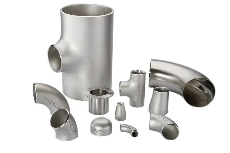
90° Elbow Specification & Dimension Table

Nominal Diameter DN | 25 | 32 | 40 | 50 |
|---|---|---|---|---|
Bending Radius | 75 | 90 | 100 | 110 |
Nominal Diameter DN | 70 | 80 | 100 | 125 |
Bending Radius | 115 | 120 | 150 | 190 |
Nominal Diameter DN | 150 | 200 | 250 | 300 |
Bending Radius | 225 | 300 | 375 | 450 |
U-Type Elbow Dimension Table

Nominal Diameter DN | 50 | 70 | 80 | 100 | 125 | 150 | 200 | 250 |
|---|---|---|---|---|---|---|---|---|
Length L ≤ | 220 | 230 | 240 | 300 | 380 | 450 | 600 | 750 |
Height | 110 | 115 | 120 | 150 | 190 | 225 | 300 | 375 |
Elbows of other angles and special-shaped elbows can be customized according to customer requirements.
Tee & Cross Fitting Dimension Table

Nominal Diameter DN | 25 | 32 | 40 | 50 | 70 | 80 | 100 | 125 | 150 | 200 | 250 | 300 |
|---|---|---|---|---|---|---|---|---|---|---|---|---|
Standard Length L | 180 | 190 | 210 | 230 | 260 | 280 | 300 | 330 | 380 | 480 | 580 | 620 |
Standard Height H | 90 | 95 | 105 | 115 | 130 | 140 | 150 | 165 | 190 | 240 | 290 | 310 |
Multi-way fittings and other special-shaped fittings can be customized according to customer requirements.
Reducer Specification & Dimension Table

Nominal Diameter DN | 25/50 | 40/70 | 50/80 | 50/100 | 70/100 | 50/125 | 80/100 | 100/150 |
|---|---|---|---|---|---|---|---|---|
Standard Length L | 150 | 150 | 150 | 150 | 150 | 150 | 150 | 150 |
Nominal Diameter DN | 80/200 | 100/200 | 150/200 | 100/250 | 150/250 | 200/250 | 300/350 | 300/400 |
Standard Length L | 200 | 200 | 200 | 250 | 250 | 250 | 250 | 250 |
Non-standard reducers and special-shaped fittings of various sizes can be customized as customer requirements.
Physical & Chemical Performance & Test Data
Basic Temperature, Pressure & Medium Parameters
Parameter Item | Value |
|---|---|
Nominal Pressure | PN ≤ 20kg/cm² |
Thermal Shock Tolerance | Δt=200℃ |
Operating Temperature Range | -30℃ ~ +300℃ |
Sudden Temperature Resistance | -120℃ |
Cold Shock Tolerance | Δt=180℃ |
Compatible Media | Nitric acid, sulfuric acid, hydrochloric acid, oxalic acid and all kinds of organic & inorganic chemical substances |
Incompatible Media | Fluorides, alkaline solution above 10% concentration, hydrofluoric acid, hot concentrated phosphoric acid |
Alkali Corrosion Test
Medium | Concentration | Temperature | Duration | Glass Weight Loss |
|---|---|---|---|---|
Sodium hydroxide | 5% | 50℃ | 4 hours | 0.0295mg/cm² |
Acid Solution Corrosion Test
Acid Type | Concentration | Boiling Time | Glass Weight Loss | Enamel Weight Loss under Same Condition |
|---|---|---|---|---|
Sulfuric acid | 10% | 4 hours | 0.0085mg/cm² | 0.17mg/cm² |
Hydrochloric acid | 15% | 4 hours | 0.0077mg/cm² | 0.165mg/cm² |
Nitric acid | 15% | 4 hours | 0.0053mg/cm² | 0.156mg/cm² |
Impact Resistance Test
Test condition: 2kg steel ball free fall, ball drop method
Spec | Drop Height | Test Result |
|---|---|---|
DN×L 50×500 | 350mm | Glass layer intact |
DN×L 80×500 | 450mm | Glass layer intact |
DN×L 100×500 | 500mm | Glass layer intact |
DN×L 150×500 | 600mm | Glass layer intact |
Bending Strength Test
Test condition: Universal testing machine, support spacing 700mm
Spec | Equipment | Load | Test Result |
|---|---|---|---|
DN25 | Universal testing machine | 300kg | Glass layer intact |
DN40 | Universal testing machine | 700kg | Glass layer intact |
Pressure Resistance Test
Spec | Test Condition | Test Result |
|---|---|---|
DN50mm×100mm | Pressurized to 20kg, hold pressure for 3 minutes | No rupture |
Thermal Shock Resistance Test
Specimen: DN50×120
Times | Temperature Cycle | Result | Remarks |
|---|---|---|---|
1 | -20℃ ↔ 100℃ | No cracking | Oil bath heating & cooling |
4 | -20℃ ↔ 200℃ | No cracking | Oil bath heating & cooling |
1 | 100℃ ↔ -20℃ | No cracking | Muffle furnace heating |
3 | 200℃ ↔ -20℃ | No cracking | Muffle furnace heating |
Pipe Fitting Dimension Table
Tee & Cross Dimension Table
Nominal DN | 25 | 32 | 40 | 50 | 70 | 80 | 100 | 125 | 150 | 200 | 250 | 300 |
|---|---|---|---|---|---|---|---|---|---|---|---|---|
Standard Length L | 180 | 190 | 210 | 230 | 260 | 280 | 300 | 330 | 380 | 480 | 580 | 620 |
Standard Height H | 90 | 95 | 105 | 115 | 130 | 140 | 150 | 165 | 190 | 240 | 290 | 310 |
Reducer Dimension Table
Group 1 Standard Length L=150mm
Nominal DN | 25/50 | 40/70 | 50/80 | 50/100 | 70/100 | 50/125 | 80/100 | 100/150 |
|---|---|---|---|---|---|---|---|---|
Standard Length L | 150 | 150 | 150 | 150 | 150 | 150 | 150 | 150 |
Group 2
Nominal DN | 80/200 | 100/200 | 150/200 | 100/250 | 150/250 | 200/250 | 300/350 | 300/400 |
|---|---|---|---|---|---|---|---|---|
Standard Length L | 200 | 200 | 200 | 250 | 250 | 250 | 250 | 250 |
Remarks: Non-standard reducers and special-shaped fittings of various sizes can be customized according to customer requirements.
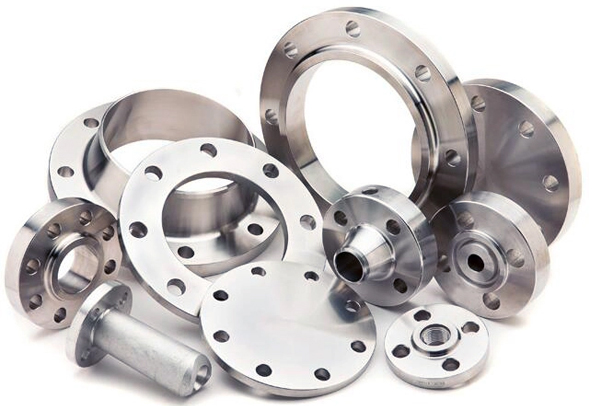
Flange Machining Dimension Table

DN | Φ Pipe OD | S Wall Thickness | D Flange OD | D1 Bolt Circle Dia | D2 Seal Dia | D3 Inner Hole | F Seal Thickness | d Bolt Hole Dia | K Bolt Circle Dia | L Bolt Length | n Bolt Qty | H Flange Thickness |
|---|---|---|---|---|---|---|---|---|---|---|---|---|
20 | 25 | 3.5 | 105 | 56 | 46 | 17 | 1 | 26 | 75 | 14 | 4 | 14 |
25 | 32 | 3.5 | 115 | 68 | 56 | 22 | 1 | 33 | 85 | 14 | 4 | 14 |
32 | 38 | 3.5 | 135 | 78 | 66 | 28 | 1 | 39 | 100 | 18 | 4 | 16 |
40 | 45 | 3.5 | 145 | 86 | 74 | 35 | 1.5 | 46 | 110 | 18 | 4 | 16 |
50 | 57 | 4 | 160 | 100 | 84 | 46 | 1.5 | 59 | 125 | 18 | 4 | 18 |
70 | 76 | 4 | 180 | 122 | 110 | 63 | 1.5 | 78 | 145 | 18 | 4 | 20 |
80 | 89 | 4.5 | 195 | 136 | 118 | 75 | 1.5 | 91 | 160 | 18 | 4 | 20 |
100 | 108 | 5 | 215 | 155 | 140 | 93 | 1.5 | 110 | 180 | 18 | 8 | 22 |
125 | 133 | 5.5 | 245 | 185 | 170 | 117 | 2 | 135 | 210 | 18 | 8 | 24 |
150 | 159 | 6 | 280 | 210 | 196 | 143 | 2 | 161 | 240 | 23 | 8 | 26 |
175 | 195 | 6 | 310 | 240 | 224 | 176 | 2 | 197 | 270 | 23 | 8 | 26 |
200 | 219 | 8 | 335 | 266 | 252 | 195 | 2 | 222 | 295 | 23 | 8 | 28 |
225 | 245 | 8 | 365 | 295 | 279 | 221 | 2 | 248 | 325 | 23 | 8 | 30 |
250 | 273 | 8 | 390 | 320 | 304 | 246 | 3 | 276 | 350 | 23 | 12 | 30 |
300 | 325 | 9 | 440 | 368 | 350 | 295 | 3 | 328 | 400 | 23 | 12 | 34 |
350 | 377 | 9 | 500 | 428 | 410 | 347 | 3 | 381 | 460 | 23 | 16 | 40 |
400 | 426 | 10 | 565 | 480 | 460 | 390 | 3 | 430 | 515 | 25 | 16 | 48 |
450 | 480 | 10 | 615 | 530 | 510 | 440 | 4 | 485 | 565 | 25 | 20 | 48 |
500 | 530 | 10 | 670 | 585 | 567 | 490 | 4 | 535 | 620 | 25 | 20 | 50 |
Material Selection, Processing & QC Requirements
1 | Pipes and plates shall adopt ordinary low carbon steel grade A3 as preferred material. |
2 | All inner corners of fittings shall be rounded, lining surfaces shall be flattened, and elbows shall be free of wrinkles. |
3 | Sleeves shall be glass-lined before welding. When welding pipes together, submerge sleeves in water during welding to prevent glass cracking from thermal shock. The inner wall of cast iron fittings shall be free of lumps. |
4 | The large end of reducers shall not exceed DN300mm, small end shall not be smaller than DN25mm, the ratio of large to small diameter shall not exceed 3, and total length shall not exceed 500mm. |
5 | The sourcing process of glass-lined steel products includes material selection, welding, rust removal, glass blowing and inspection. The protruding glass on flange sealing surface is ground flat. |
6 | Adopt mutual inspection and multi-inspection system. Finished products shall be frequently inspected by spark detector for flaw detection. |
Installation, Handling & Operation Notes
1 | The structural strength is sufficient for normal installation. However, excessive concentrated load, impact, improper clamping & loading/unloading, and collision of flange sealing faces will damage the inner glass lining. |
2 | Welding, cutting or local flame heating on glass-lined steel products is prohibited. |
3 | Use high-quality rubber wrapped gaskets, PTFE wrapped gaskets, PTFE sheets and modified PTFE sealing gaskets during installation. Gasket thickness ≥4mm, and gasket outer diameter shall be larger than flange raised face. |
4 | Coat both sides of the gasket evenly with corrosion-resistant & wide-temperature adhesive, and place the gasket correctly. Tighten bolts evenly to avoid uneven stress which may damage flange glass sealing surface. After installation pressure test, flush the pipeline with compressed air and water to remove ash residue and other residual impurities. |